TB-2507 · REV E · Technical newsheet
Electronic TestDevice profile
1 GHz, 12-bit MXO3 Turns RF Current Probes Into Bench EMC Pass/Fail Tool
Six to eight microamps of cable harmonic current can fail FCC Class B. Ken Wyatt shows how an R&S MXO38 plus a calibrated RF current probe estimates E-field margins on the bench.
By Grace Kim5 min read926 words
Features
- R&S MXO38: 1 GHz bandwidth, 12-bit, 500 Mpts memory, 4.5 million waveforms/s capture, 21 ns trigger re-arm
- Tekbox TBCP2-750 RF current probe costs $879 with 30 kHz–400 MHz (3 dB) bandwidth
- 6–8 µA of harmonic cable current can fail FCC Class B
- Worked example: 8 dBµA at 120 MHz predicts 42.03 dBµV/m vs. 43.5 dBµV/m limit — only 1.47 dB margin
- EMC standards specify RBW of 100 kHz (military) or 120 kHz (commercial); Wyatt uses 1 MHz for troubleshooting
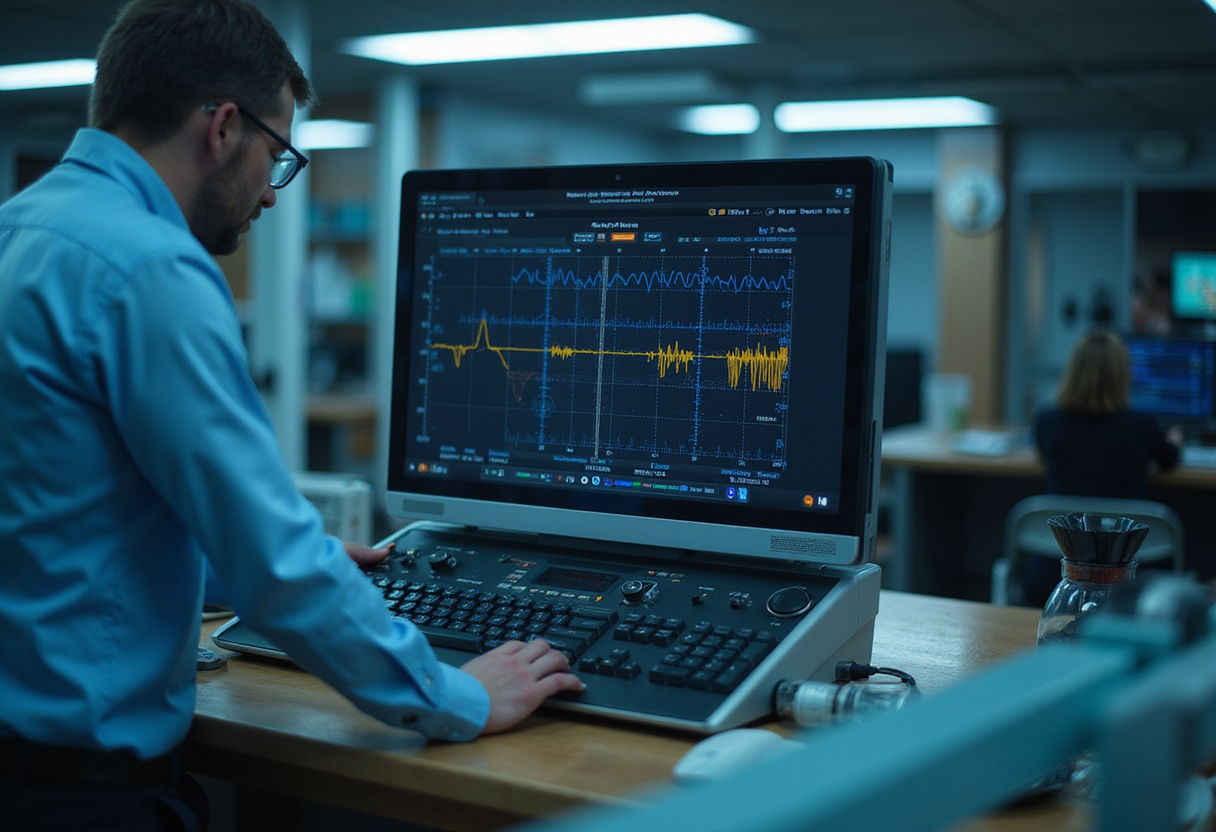
Six to eight microamps of harmonic current on a single cable can fail FCC Class B — and the Rohde & Schwarz MXO3 oscilloscope, paired with an RF current probe, measures that current on a bench without a shielded chamber. That is the core of Ken Wyatt's second article in his series on using the 1 GHz, 12-bit MXO3 for EMC measurements.
The R&S MXO38 Wyatt tested offers 1 mV low-noise vertical sensitivity, 500 Mpoints of memory depth, and a 21 ns trigger re-arm time. The waveform capture rate reaches 4.5 million waveforms per second, which Wyatt says provides real-time capture of up to 99% of events — effectively near-real-time spectrum capture for EMC troubleshooting.
Why cables, not boards, usually fail the test?
Cable radiation is usually the dominant reason for radiated emission failures, Wyatt writes. Harmonic energy sources on the board — processors, memory, power conversion — couple onto attached I/O and power cables. The high-frequency harmonic currents then turn the cable into an antenna.
His three-step troubleshooting process addresses this in sequence: near-field probing of board sources (Step 1, covered in Part 1), RF current probing of attached cables (Step 2, this article), and subsequent mitigation. The RF current probe characterizes and reduces the coupled currents by clamping around each cable in turn and recording its spectrum.
What makes an RF current probe different?
Conventional oscilloscope or DMM current probes have small apertures and top out around 100 MHz. RF current probes measure microamps of RF current from kHz to hundreds of MHz on I/O and power cables, with a hinged aperture that accepts anything from a single wire to large-diameter cable. Wyatt used the Tekbox Model TBCP2-750 at $879, whose 3 dB bandwidth spans 30 kHz to 400 MHz.
The probe is a current transformer: the cable under test is the primary, the secondary is loaded by the 50 Ω input of the spectrum analyzer, producing an output in dBµV. Switching the MXO38 spectrum display from its default dBm to dBµV allows direct comparison with emissions limits.
Practical technique matters. Wyatt slides the probe along the cable to maximize dominant harmonics (cable resonances shift with position), then tapes it to the bench. He centers the cable in the aperture with bubble wrap to keep it away from the metal probe case and minimize measurement error.
How did he set up the measurement?
The test object was the power input cable of a 1 MHz GaN buck converter with a strong 230 MHz ring frequency. Wyatt first performed an ambient capture with the EUT off — the probe plus cable acts as a receiving antenna, and AM/FM broadcast, two-way radio, DTV, and cellular signals will otherwise corrupt the measurement. He noted you should see at least the FM broadcast stations between 88 and 108 MHz.
On the MXO38: connect the probe to channel 1, set termination to 50 Ω, enable Spectrum mode, and set Start = 0, Stop = 1 GHz. EMC standards specify RBW of 100 kHz (military) or 120 kHz (commercial), but Wyatt prefers 1 MHz for a cleaner averaged troubleshooting signal. Max Hold captures are saved as reference traces: R1 "Ambient" and R2 "EUT_On." One UI quirk: the Reference screen defaults its source back to C1 on each reopening, so the user must reselect S1MaxH or a time-domain reference gets stored instead.
The blue trace in his capture shows broad peaks at the 233 MHz ring frequency and a 558 MHz board resonance. Adding a Fair-Rite 43 material snap-on choke demonstrated immediate harmonic-current reduction, visible against the saved references.
Can you estimate pass/fail before the test lab?
This is the method's practical payoff. Commercial RF current probes ship with a calibration chart of transfer impedance versus frequency. Combining that chart with Ohm's Law and the E-field model from Clayton Paul and Henry Ott yields a ballpark E-field prediction at the compliance test distance (3 m or 10 m).
Wyatt's worked example: a dominant harmonic measures 28 dBµV at 120 MHz at the analyzer; the probe chart reads 20 dBΩ transfer impedance at that frequency. The common-mode current is therefore 28 − 20 = 8 dBµA. Plugging current, frequency, cable length, and distance into the Paul/Ott equation gives an E-field of 42.03 dBµV/m. The FCC Class B limit at 120 MHz is 43.5 dBµV/m — a margin of just 1.47 dB. Wyatt's rule of thumb calls for at least 6 dB margin, so this product would likely fail. A downloadable Excel spreadsheet from his website automates the calculation.
The estimates are not precise; Wyatt frames them as ballpark comparisons. But they are measured performance derived from a calibrated transfer impedance, not a datasheet claim, and sufficient to decide whether mitigation is needed before booking chamber time.
What does this change for pre-compliance workflows?
Wyatt's verdict on the instrument itself: with its fast acquisition update rate, the MXO38 spectrum feature works extremely well for bench-top EMC troubleshooting, and setup is "a step ahead of other leading manufacturers." Saved reference waveforms persist in memory along with the instrument setup, so relocating the bench preserves the entire session.
The larger question the article raises for engineering teams: if cables dominate radiated failures and a $879 probe plus a well-specified oscilloscope predicts compliance margins within a few decibels, how much of the pre-compliance iteration loop still justifies repeated trips to a third-party test lab?
via eeworldonline.com (Original)
Filed under
- emc-troubleshooting
- oscilloscope
- pre-compliance-testing
- rf-current-probe
- spectrum-analysis
More from Grace Kim
Show full bio
Correspondent covering consumer brands and retail at Testbench Report.
67 articles
Application notes
- EU Commission Clears $86M for Semiconductor Test Equipment Site
- Modern Test Equipment Targets Accurate Power Cable Fault Location
- LAPP Develops Condition-Based Monitoring for Power and Control Cables
- Emerson widens access to RF test systems with new NI PXI instruments
- Square Waves on the Scope: Armani's Bench Method for Amplifier Testing